

 By Mr.Sun
A gasket seals an assembled joint, not an isolated casting. The machined land must work with the gasket, opposing face, fasteners and operating conditions. A drawing that specifies only a general surface finish can leave important questions about contact width, interruptions and compression unresolved.
The casting route should preserve enough material and access to produce the required sealing geometry. However, machining allowance is only the starting point. The final acceptance plan needs to evaluate the actual interface that the gasket will contact.
Identify the active sealing area
Mark the gasket contact region on the drawing. Bolt holes, nearby openings and edge breaks can interrupt or reduce that area. A visually broad flange may contain a much narrower effective land once the gasket position and assembly tolerances are considered.
The gasket supplier’s design requirements should guide the interface specification. Avoid assuming that a wider land, a smoother finish or greater compression is always better. Different sealing systems have different requirements, and the approved assembly design should determine the target.
Separate flatness, texture and damage
Flatness describes a form requirement; roughness describes surface texture under a specified measurement method. A scratch crossing the sealing path is another concern again. One favorable roughness reading does not demonstrate that the entire land is flat or free from damaging local marks.
The inspection plan should address these characteristics separately where relevant. It should identify the measured region, the manufacturing condition and how local damage is assessed. This is more useful than a broad instruction that the flange must look smooth.
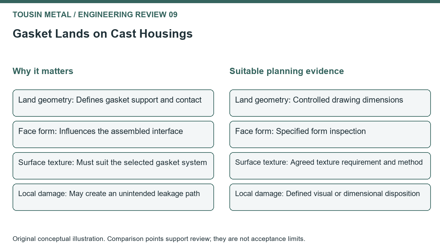
| Interface characteristic | Why it matters | Suitable planning evidence |
|---|---|---|
| Land geometry | Defines gasket support and contact | Controlled drawing dimensions |
| Face form | Influences the assembled interface | Specified form inspection |
| Surface texture | Must suit the selected gasket system | Agreed texture requirement and method |
| Local damage | May create an unintended leakage path | Defined visual or dimensional disposition |
Review the fastener and flange system together
A casting flange can deform under assembly loads. The designer should assess the joint as a system rather than trying to solve every sealing concern through a surface callout. Bolt arrangement, flange stiffness and the gasket’s behavior belong in that assessment.
If the mating component is outside the casting supplier’s scope, its interface information is still relevant. A supplier cannot validate the complete joint from one flange drawing alone. The purchasing package should distinguish component inspection from any agreed assembled sealing test.
Protect the finished land between operations
The machining operation may produce an acceptable face that is later damaged by stacking, clamping or packaging. Define how the land is handled after finishing. Protective materials should not introduce residues that interfere with the gasket or the intended service.
Inspection timing matters as well. A check immediately after machining confirms that stage, while a final dispatch check addresses subsequent handling. The appropriate plan depends on the route and the risk of damage, but the records should make the inspection stage clear.
Use a representative assembly when validating a change
Suppose an edge break is enlarged to improve handling. If it reduces the effective gasket contact region, a seemingly minor machining change may affect the seal. Review such changes against the actual gasket position and tolerance stack before approving them.
For housing enquiries to Tousin Metal, include the gasket contact sketch, relevant mating geometry and acceptance requirements. This helps the foundry and machinist protect the correct region and avoids relying on a general-purpose finish note for a specific sealing function.
Design resources
Trelleborg: Gasket Product and Design Selector illustrates the relationship between gasket and flange design inputs. Trelleborg: Design Support and Engineering Tools provides further manufacturer resources. Use the requirements for the actual selected sealing system rather than a generic value.


