

 By Mr.Sun
A bolt can reach the bottom of a blind hole before it clamps the joint. The assembler may feel resistance and apply the specified torque even though the intended contact has not been established. Avoiding that situation requires more than a nominal thread size on the casting drawing.
Blind tapped holes need a coordinated definition of usable thread, drilled depth, fastener length and assembly stack. Cleaning and trapped material also deserve attention because the bottom of the hole can be difficult to inspect after machining.
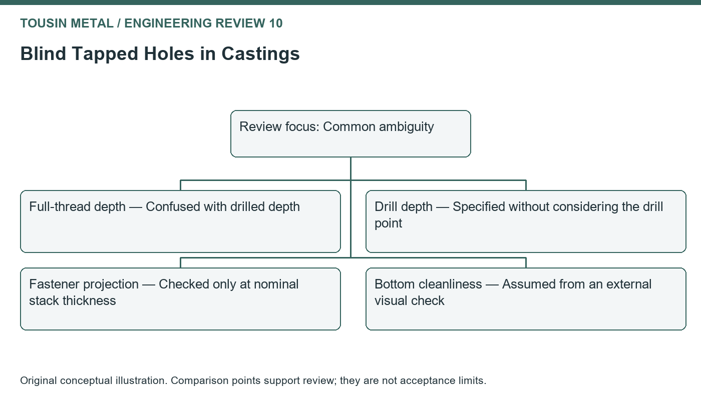
Distinguish full thread from tool travel
The tap does not necessarily produce a complete thread to the deepest point it reaches. The drilling geometry and tapping method determine the space needed beyond the usable thread. A drawing should therefore identify the required full-thread depth rather than treating the overall hole depth as the engagement length.
The machining supplier must confirm that the specified depths fit within the available casting wall. Extending the drilled hole to gain clearance may reduce a pressure boundary or break into a nearby passage. That decision should be reviewed against the complete component geometry.
Evaluate the assembled stack at its limits
Fastener length, washer thickness, mating-part thickness and thread depth all contribute to the final position of the bolt. Evaluate the relevant tolerance limits rather than only the nominal dimensions. The design must provide the intended engagement without relying on bottom contact to stop the fastener.
| Dimension or condition | What it controls | Common ambiguity |
|---|---|---|
| Full-thread depth | Available usable engagement | Confused with drilled depth |
| Drill depth | Tool clearance and remaining wall | Specified without considering the drill point |
| Fastener projection | Position inside the hole | Checked only at nominal stack thickness |
| Bottom cleanliness | Available free space and contamination | Assumed from an external visual check |
A controlled stack analysis is particularly useful when a standard bolt is used across several assemblies with different mating thicknesses.
Treat trapped material as a separate issue
Chips, cleaning fluid, preservative or excess assembly compound can remain in a blind cavity. Their presence can interfere with assembly or create a contamination concern. Define the required cleanliness and drying condition, then select a verification method that can access the feature.
Do not add a vent or drain hole casually as a workshop remedy. It may change the pressure boundary, sealing behavior or structural section. If venting is necessary, the design authority should specify its position and function on the controlled drawing.
Gauge the requirement that was actually specified
A thread gauge provides evidence about the thread characteristics it is designed to check. It does not independently establish the assembled fastener clearance or confirm that the bottom is free of debris. Depth and cleanliness may need separate inspection steps.
The inspection record should identify the full-thread requirement and any depth measurement method. If access makes a requirement difficult to verify, resolve the method during process planning. A note added at final inspection cannot create clearance that the component geometry does not provide.
Validate the final fastening arrangement
An illustrative assembly check uses the actual bolt, washer and mating part to confirm seating under the approved procedure. That check should complement dimensional controls rather than replace them with a subjective judgment that the bolt feels tight.
When sending Tousin Metal a casting drawing with blind tapped features, include the full-thread depth, available wall constraints and relevant fastener stack. If the tapped feature sits near an internal passage, an interface section view is often more useful than an additional general note.
Supporting reference
Nickel Institute: Stainless Steel Fasteners—A Systematic Approach to Their Selection provides broader fastening context. The depth and stack examples in this article are engineering planning considerations; final engagement and strength requirements must come from the approved joint design.


